It is very easy to install infrared heaters.
If you are moving, you can easily remove the device and take it with you. They are compatible with all ventilation systems, as their work does not cause air flow circulation. Infrared heater is the device for heating indoor areas (stadiums, cafes, stairways, warehouses, shops, hangars, garages, factory premises, shopping centers, apartments,school & nurseries, flat, room, living and hallways, balconies, offices, houses, cottages, patios, hot yoga, churches, etc).
The heater must be installed only by qualified electrician!!!
Mounting and connection instructions
The heater must be properly installed prior to use.
1. Mount the heater to the ceiling using mounting bracket, self-tapping screws, screw nails and dowels included in the set (as indicated on the picture below).
WARNING! Mounting bracket (located under the frame of the heater) provides safe suspension of the heater to the ceiling with natural cover (wood, metal, concrete, etc). When using non-natural ceiling cover the use of mounting brackets is allowed at heat resistance of the surface material not less than 80oC.
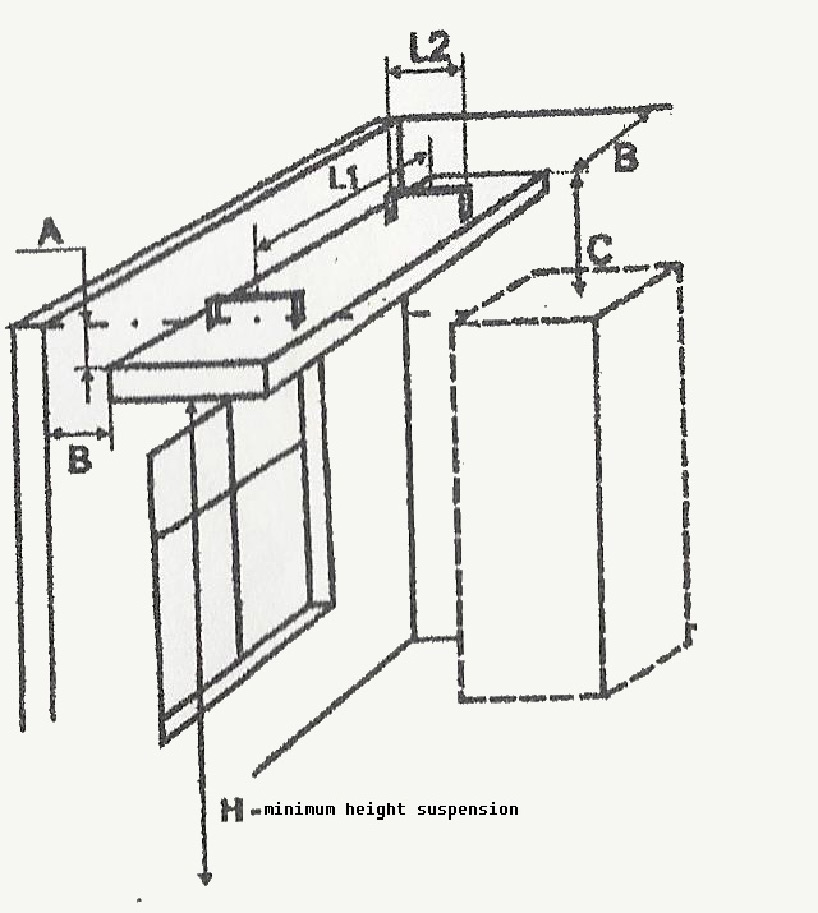
WARNING! Distance in mm: to the ceiling A (not less than 50); to the walls B (not less than 500); and objects C (not less than 500), that fall within the scope of heater operation.
Sizes for mounting on the ceiling:
|
L1, mm |
L2, mm |
H, m |
|
|
E/D 600 |
798 |
24 |
2,0 |
|
E/D 1000 |
1275 |
24 |
2,4 |
|
E/D 1300 |
1275 |
24 |
2,7 |
|
R/D 2000 |
1260 |
48 |
3,1 |
|
R/D 3000 |
1260 |
48 |
3,3 |
|
R/D 4000 |
1260 |
48 |
3,5 |
Where impossible to use standard mounting brakes for heater R and PRO3000/4000 or at the request of the customer they may be assembled with frames for ropes suspension.
2. To mount thermostat at 1,5 m height from the floor. Do not mount thermostat within the area of direct rays of the heater or other heat sources in order to avoid false operation.
3. To wipe heat radiating plate with spirit.
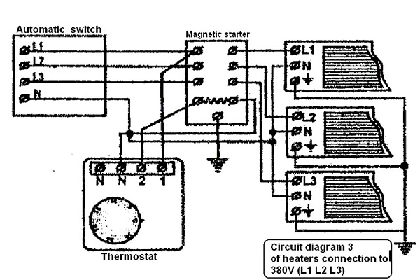
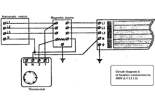
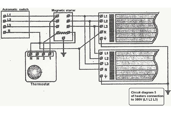
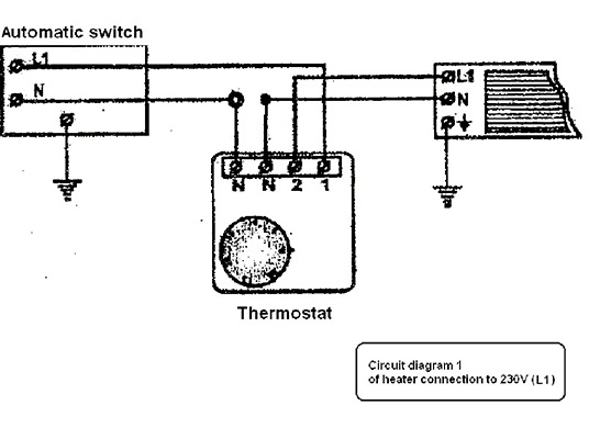
Connection
The heater must be connected only by a qualified electrician pursuant to the chosen electric circuit diagram
- E400/600/700/800, E1000/1100/1200/1300, R2000 - drawings 1-3
- R3000, R4000, R6000- drawings 4, 5
The connection is made to screw dips of terminal support.
CONNECTION OPTIONS
of the thermostat with total load up to 3,5 kW
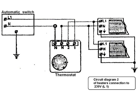
CONNECTION OPTION
of the thermostat with total load above 3,5 kW